
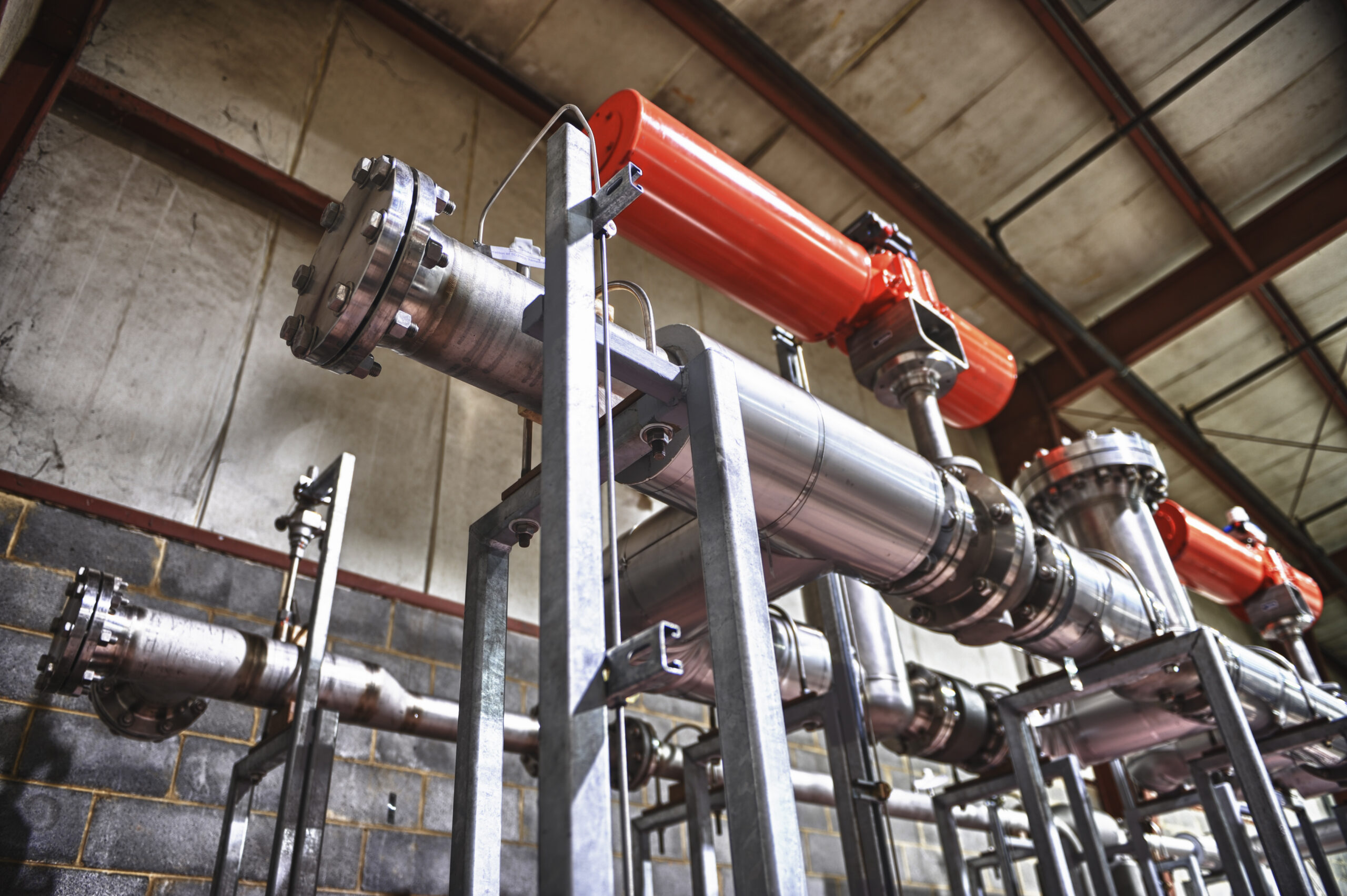
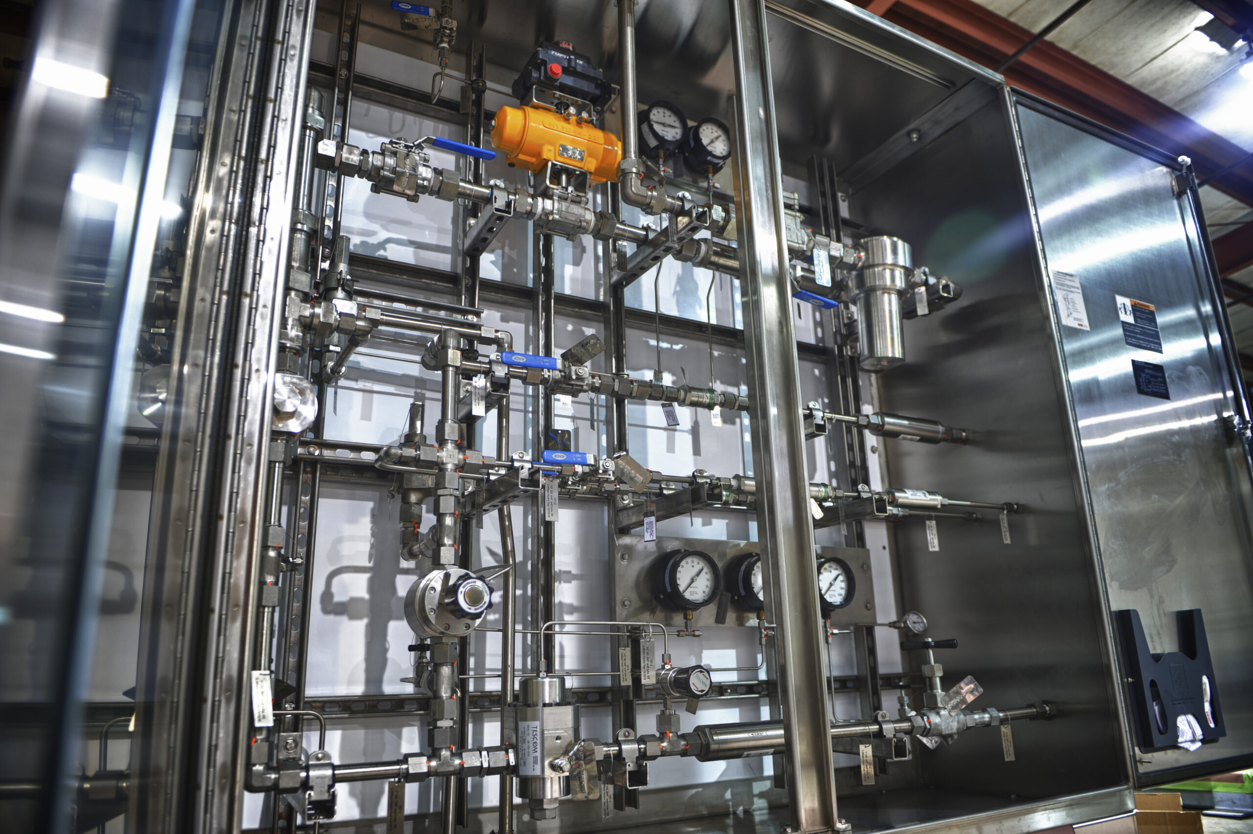
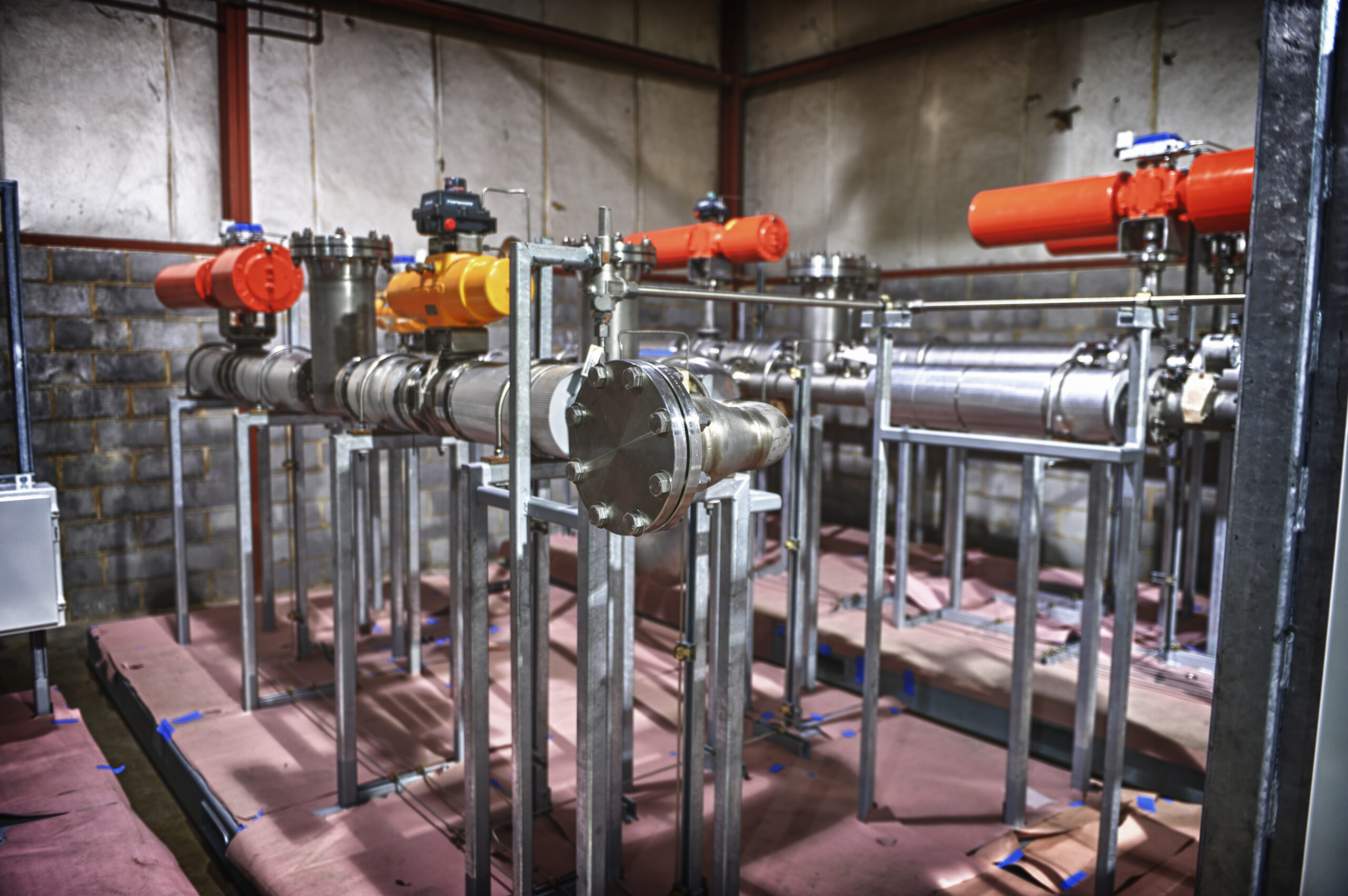
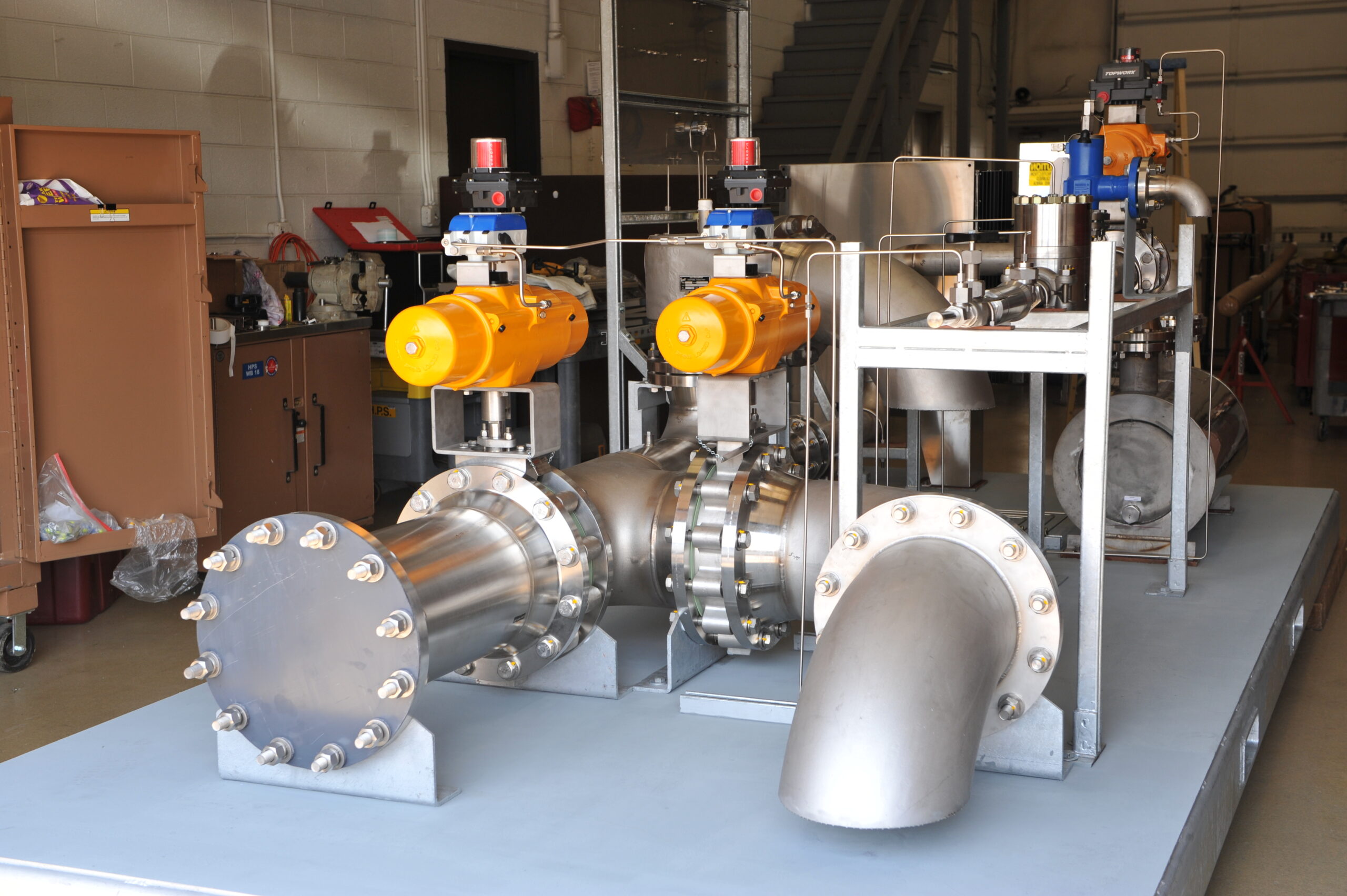
Gas purification suitcases revisited
Leave a CommentToday’s global economy benefits firms whose skills can transcend borders to address problems on a global scale.
But those opportunities come with some challenges, including international regulatory policies that aren’t in perfect sync.
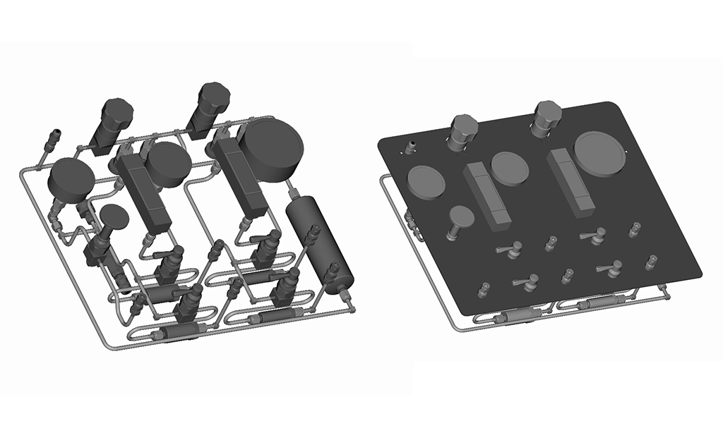
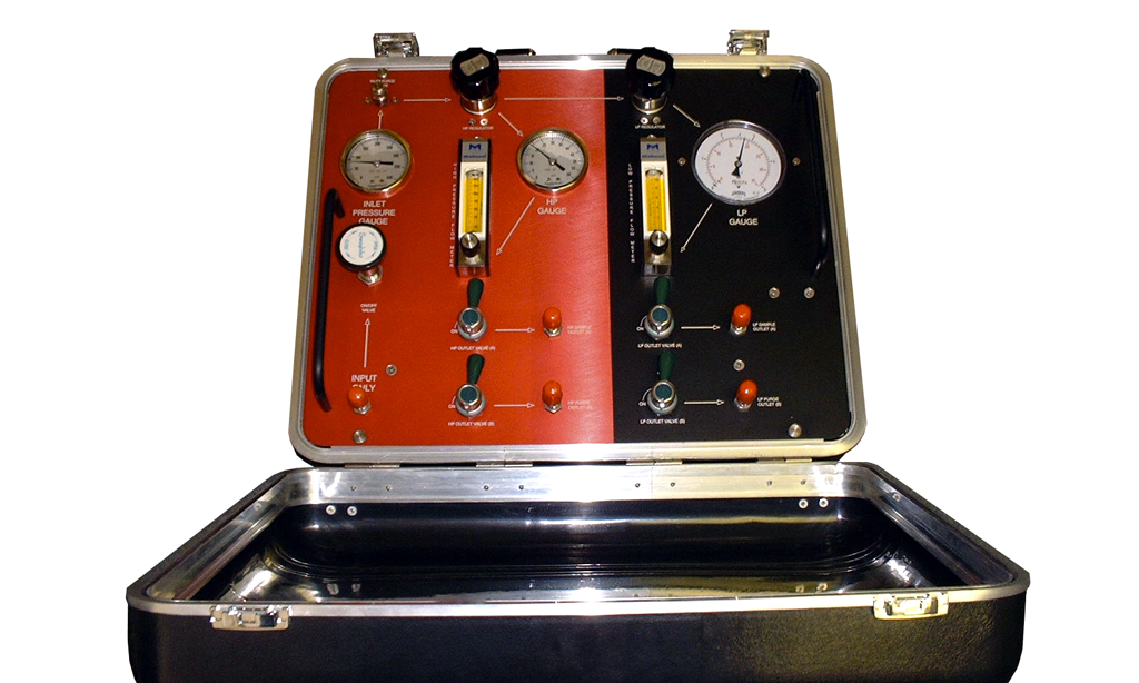
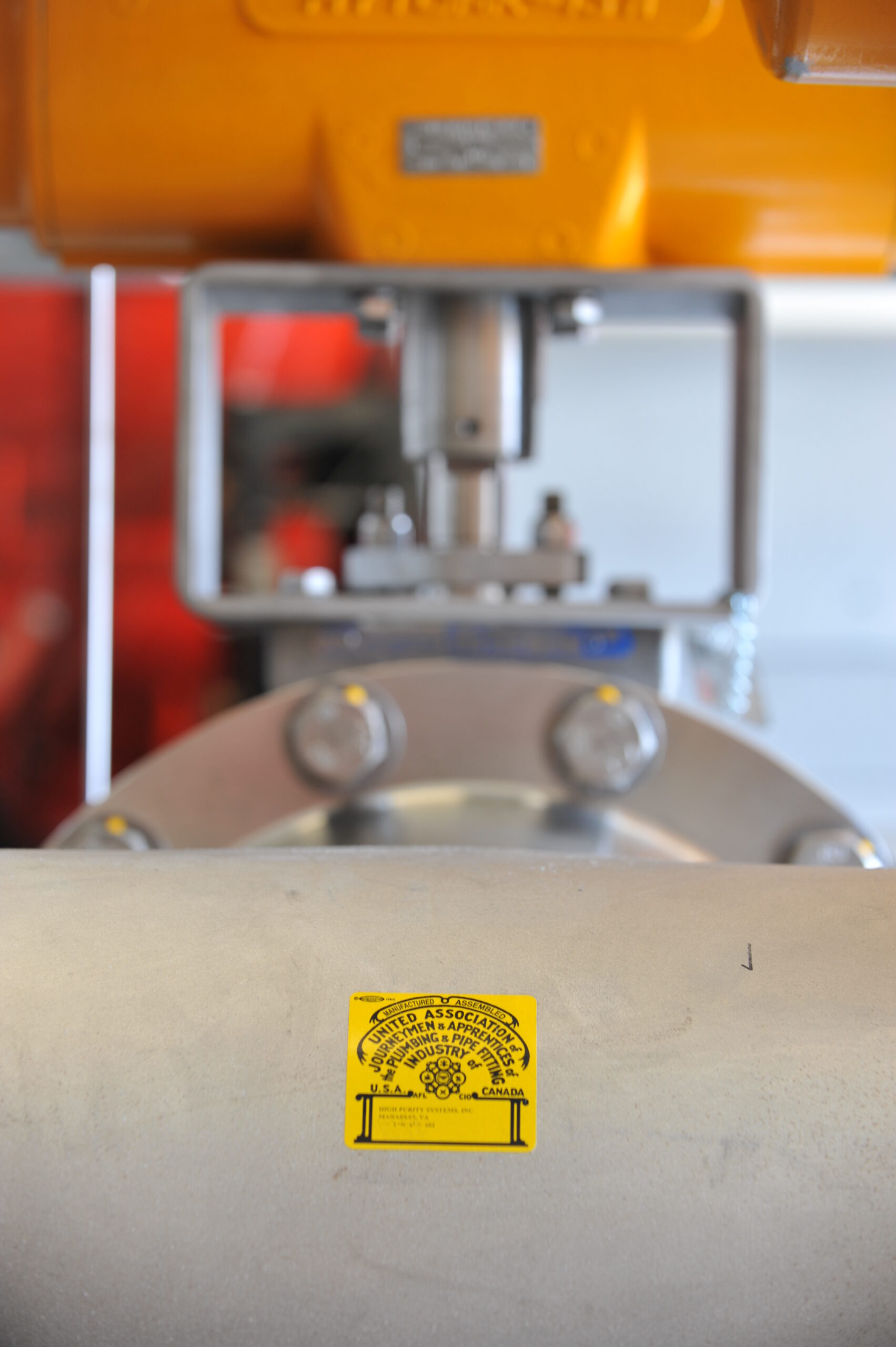
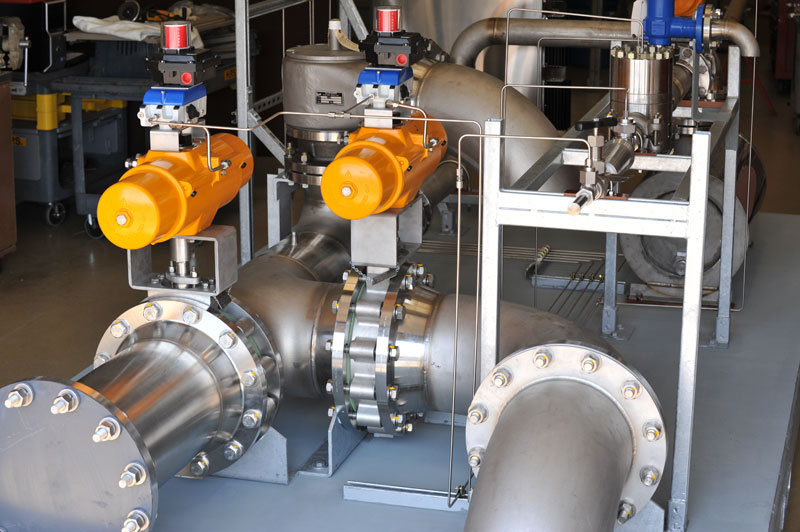
That’s the case here: Five years after High Purity Systems prototyped and then produced custom remote launch purge panels that supported satellite launch missions for NASA, we were tasked with updating these panels with specifications that made them compliant with European standards.
The Challenge
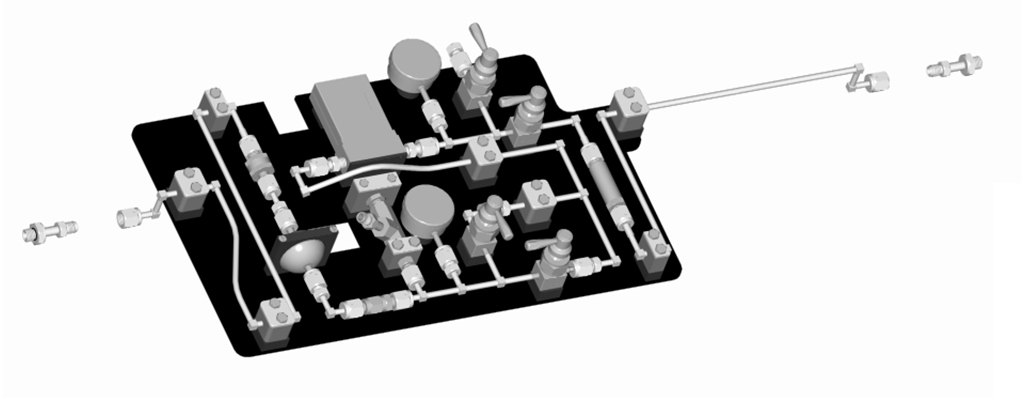
Our client’s assignment for this new project was essentially the same as it was on the NASA job: Provide ultra-high purity gas delivery capabilities for satellite launch ground support missions.
Like the U.S., the European Union has a pressure systems and vessels code standardizing the construction of gas purification panels. U.S. rules are similar, but “close enough” doesn’t cut it.
The client called on High Purity Systems hoping that our team could navigate the EU requirements as seamlessly as we’d done for the NASA job five years earlier.
The Solution
The client needed two things before it could use these purge panels in Europe. First, the panels needed to be recertified. Second, they had to comply with the EU’s recently adopted pressure and vessel standards. Those standards were codified in this directive from the European Parliament.
Conversations with the customer and a deep dive into the EU directive revealed that the unit would need updated regulators, gauges, flow meters and pressure relief valves to comply.
The requirements were straightforward enough; lead time proved to be the biggest issue. It would take two to three weeks to get the updated pressure relief valves. The regulators would take four to six weeks to arrive.
To ensure the project was not delayed, our craftsmen completed all the other required modifications in advance. As soon as the valves and regulators arrived, they were installed right away. All materials were made of 316L stainless steel and exceeded the new requirements for the EU standards. The updates (as well as required pressure and leak testing) were completed in our in-house Class 100 / Class 1000 cleanroom.
The updated panels were delivered on-time along with the required documentation stating they complied with applicable EU directives. In addition, we provided the updated panel’s technical file so that our customer could further prove it conformed to the rules.
The Result
On-time delivery of the updated panels meant that our customer could live up to its commitment to its European aerospace partners.
There’s much to be proud of in this success story. Our customer’s sterling reputation with NASA is now shared among the stakeholders in another major world space agency. The customer has made a name for itself on the world stage for its ability to deliver skillfully made UHP gas delivery equipment under any regulatory environment.
Closer to home, this project made a strong working relationship between High Purity Systems and the customer even stronger.
High Purity Systems has over three decades of experience fabricating and installing UHP gas delivery systems for aerospace, microelectronic and other critical applications.
If your current fabricator is unfamiliar with international compliance or you’re adapting a system for international service, the High Purity Systems team is ready to lend a hand. Contact us to talk it through.
Contact High Purity Systems
Have a question about a piping challenge? Want to discuss an upcoming project? Let’s talk.

Pressure Reducing Stations
Leave a CommentThe Challenge
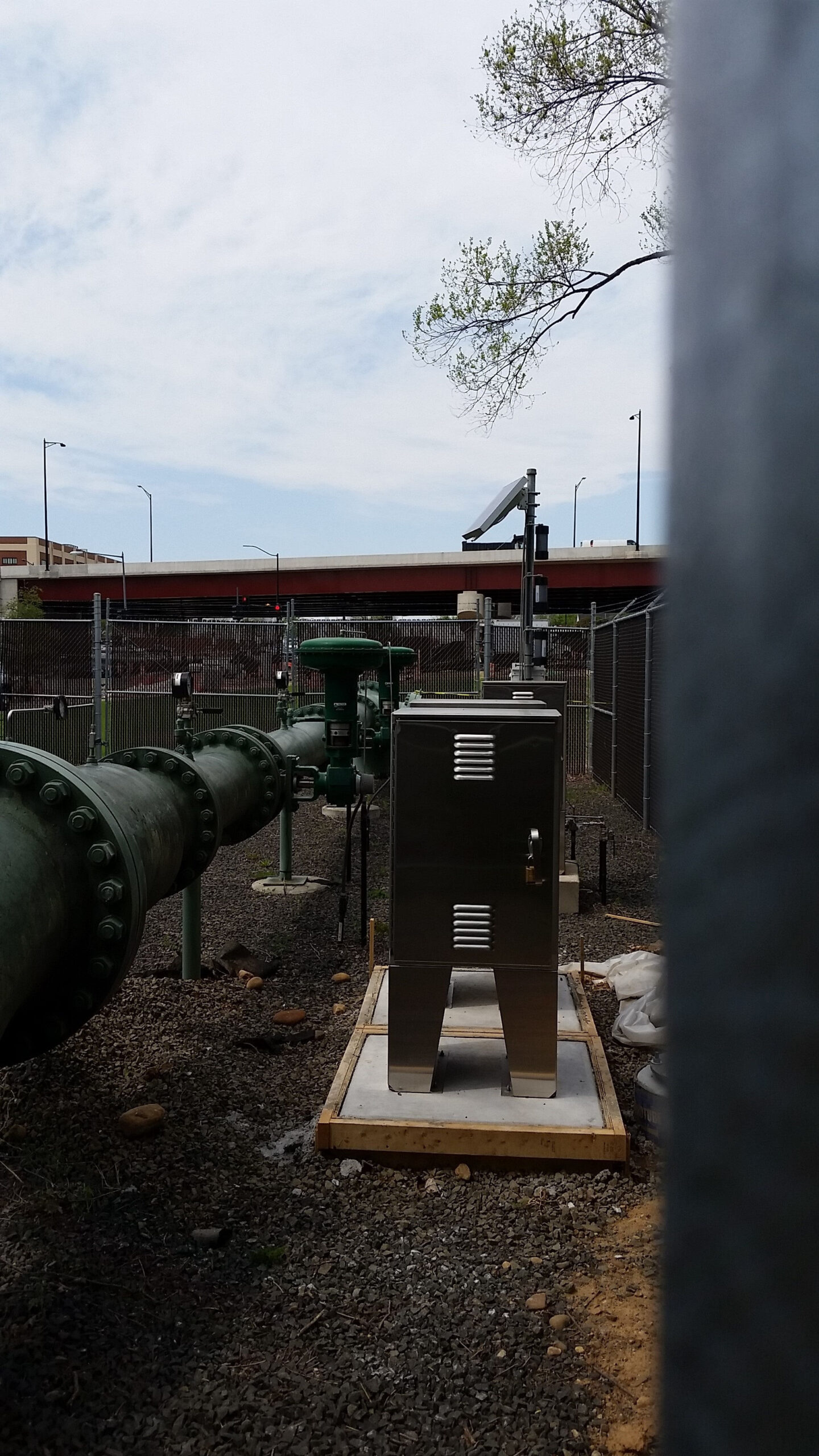
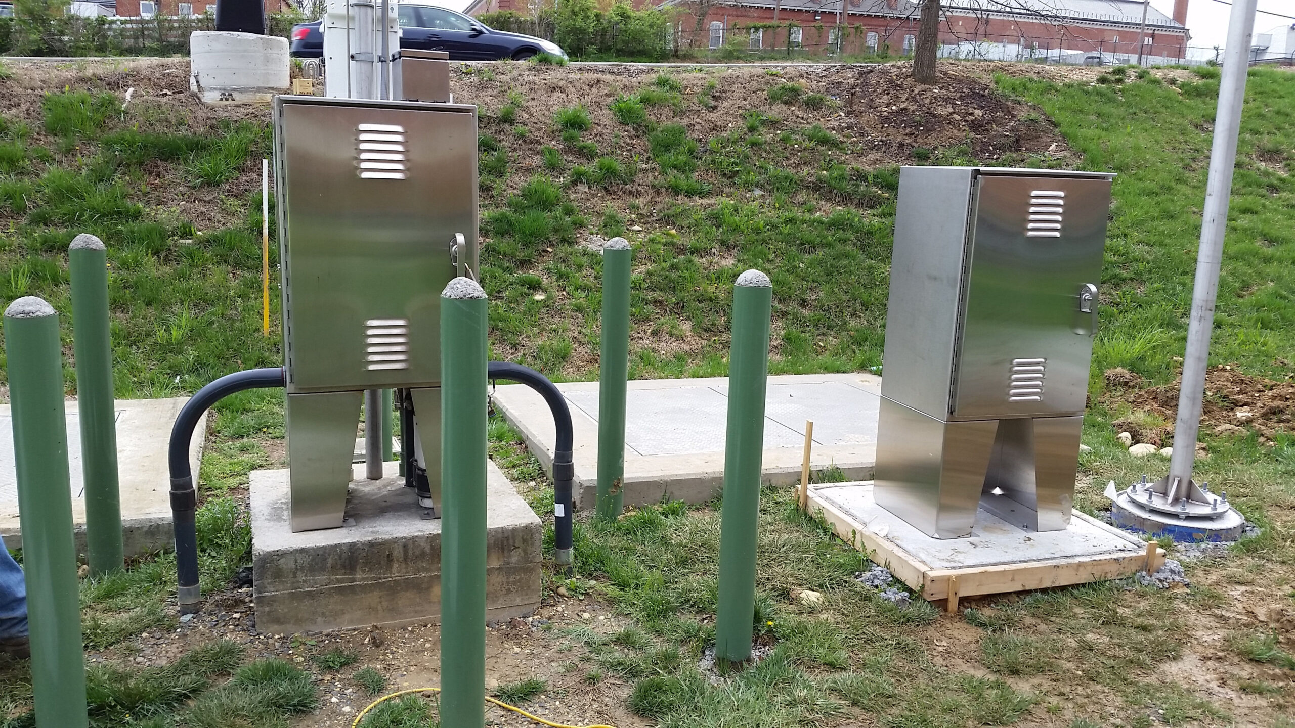
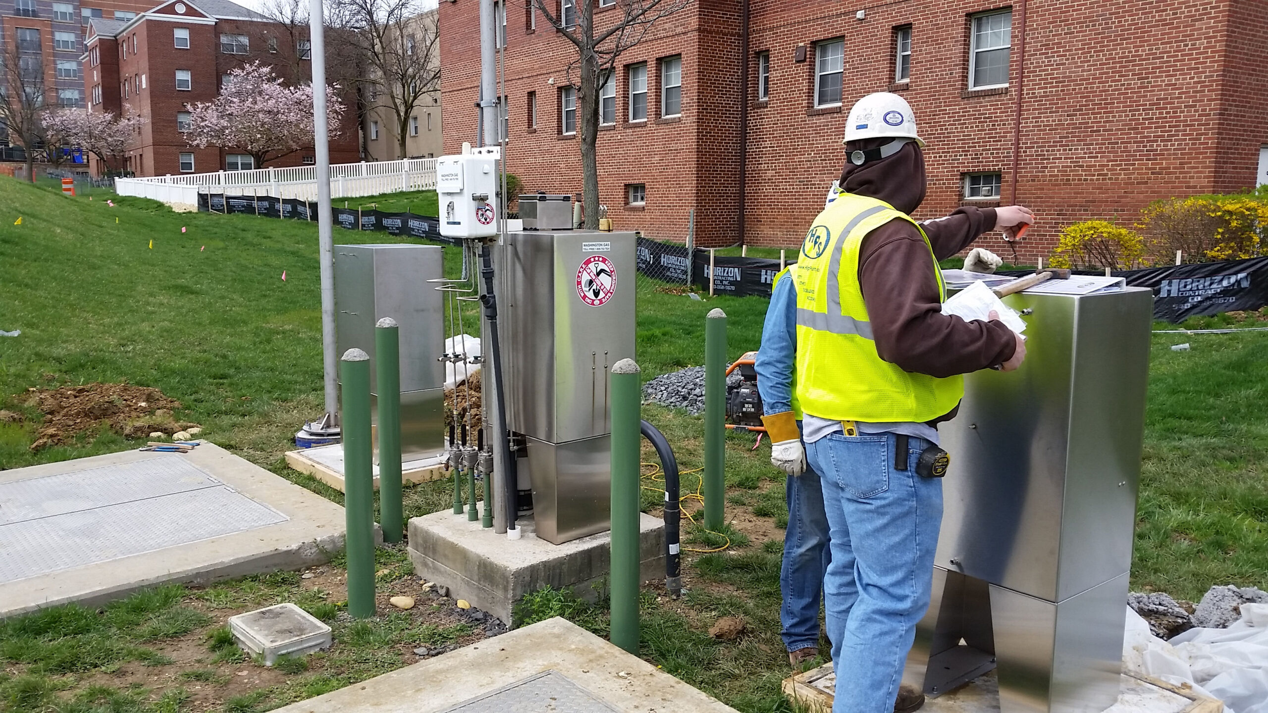
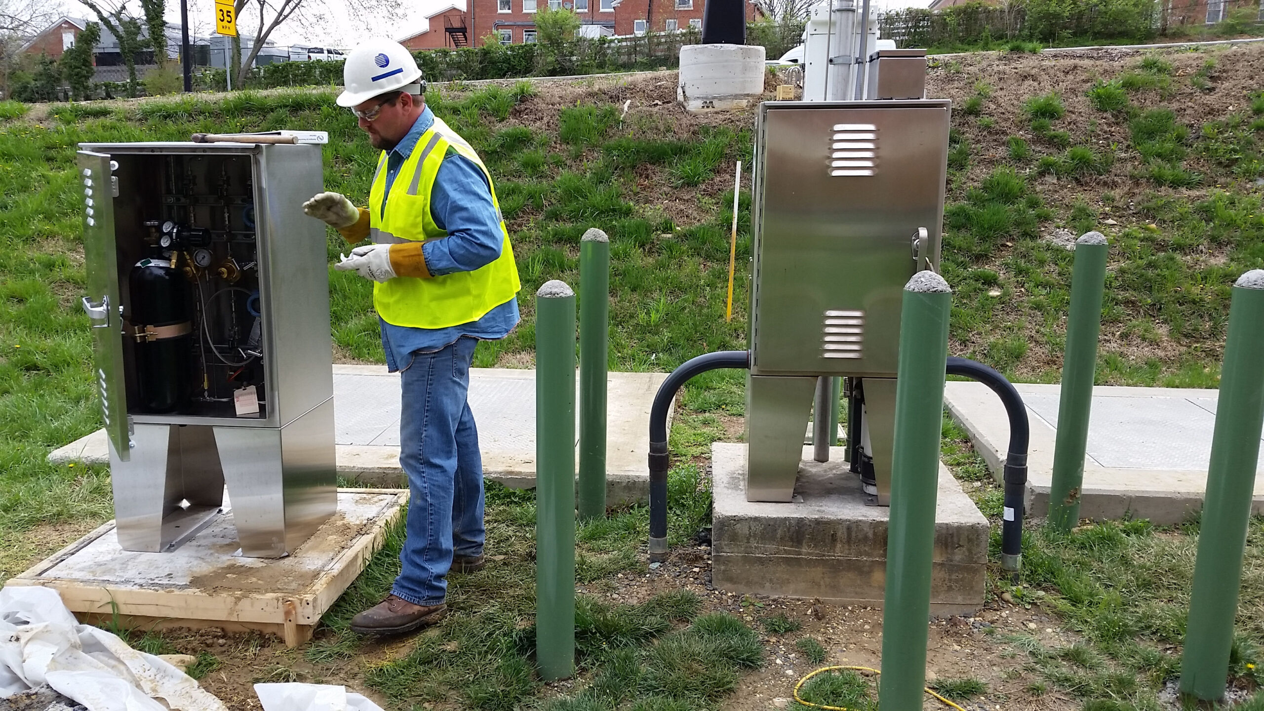
One of our customers, a 165-year veteran utilities provider, was working on a facility improvement plan across three different East Coast locations. Already familiar with HPS’ reliability, pricing, and quality from working with us on past projects, the customer turned to our team for help transitioning from a manual gas pressure relief system to one that was more automated and up to date.
The Strategy
Upon project initiation, the customer supplied us with piping and instrumentation diagrams (P&ID’s) and specifications but, as is common with projects of this nature, also asked us to assist with layout drawings. Our technical team immediately began brainstorming to develop the best solutions to address their project plans, and HPS happily submitted, modified, and ultimately received approval for our drawings of the final fabrication.
During the project we installed a total of three communication boxes and three automated control boxes to eliminate the need to manually close a valve to reduce pressure in the gas supply line — all 2 feet x 2 feet x 4 feet. One of each box was installed throughout their three East Coast facility locations. The control boxes were connected to existing gas lines through 3/8” stainless steel 304 tubing. We also installed gas regulators, pressure transmitters and gas gauges during the assembly for each control box as well as the installation of the electrical signal lines that allowed the communication box to “talk” to the control box at each location.
Our team installed solar panels that charged internal batteries to ensure the automated communication system remained connected to the main terminal. After completion, we pressure tested each of the control boxes to certify that they met customer specifications.
The Result
From start to finish, this project was completed well within the pre-determined timeframe. The customer told us they appreciated our prompt attention and return of information throughout the project, as well as our high quality of work. Let High Purity Systems provide you with the same reliability and quality on your next project.
Contact High Purity Systems
Have a question about a piping challenge? Want to discuss an upcoming project? Let’s talk.
Muffler Canisters
Leave a CommentThe Challenge
At any given time, High Purity Systems has several irons in the fire; a few of these irons fall underneath the banner of research and development (R&D). Within that category, there are two different ways in which we can help our customers.
The first is a situation in which the customer has a problem but doesn’t know the theoretical solution or how to build it practically — like our work on this digester wiper. The second scenario is one where the customer already has a design to fix their problem but needs someone to build a custom piece to see if it will function properly — such as our work on these purge suitcases.
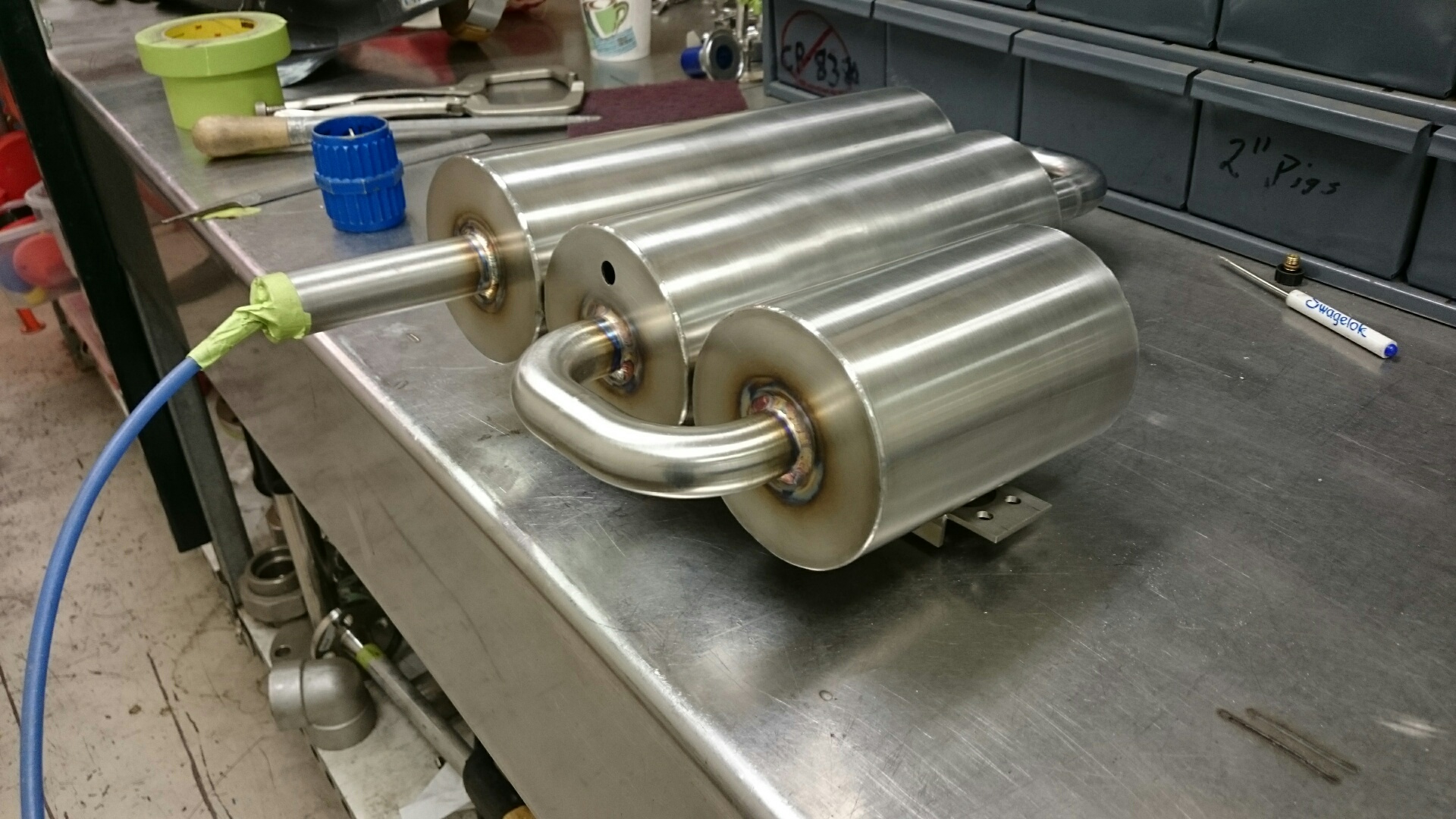
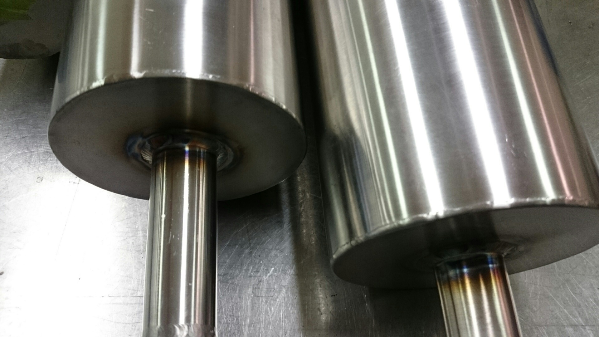
For one recent R&D project, a customer asked HPS for help building a muffler with strict precision requirements; it needed to be made from 316L stainless steel, weigh less than 2 lbs., and fit inside a pre-determined space approximately 12-14” tall by 3” wide.
The Strategy
Because of the heavy weight of stainless steel, it was suggested that we begin with a lighter 0.020” wall tubing. The thinness of this tubing made the bending difficult as the material tends to kink and flatten. Our fabrication team instead proposed an alternative solution that would allow us to bend it without any of these issues.
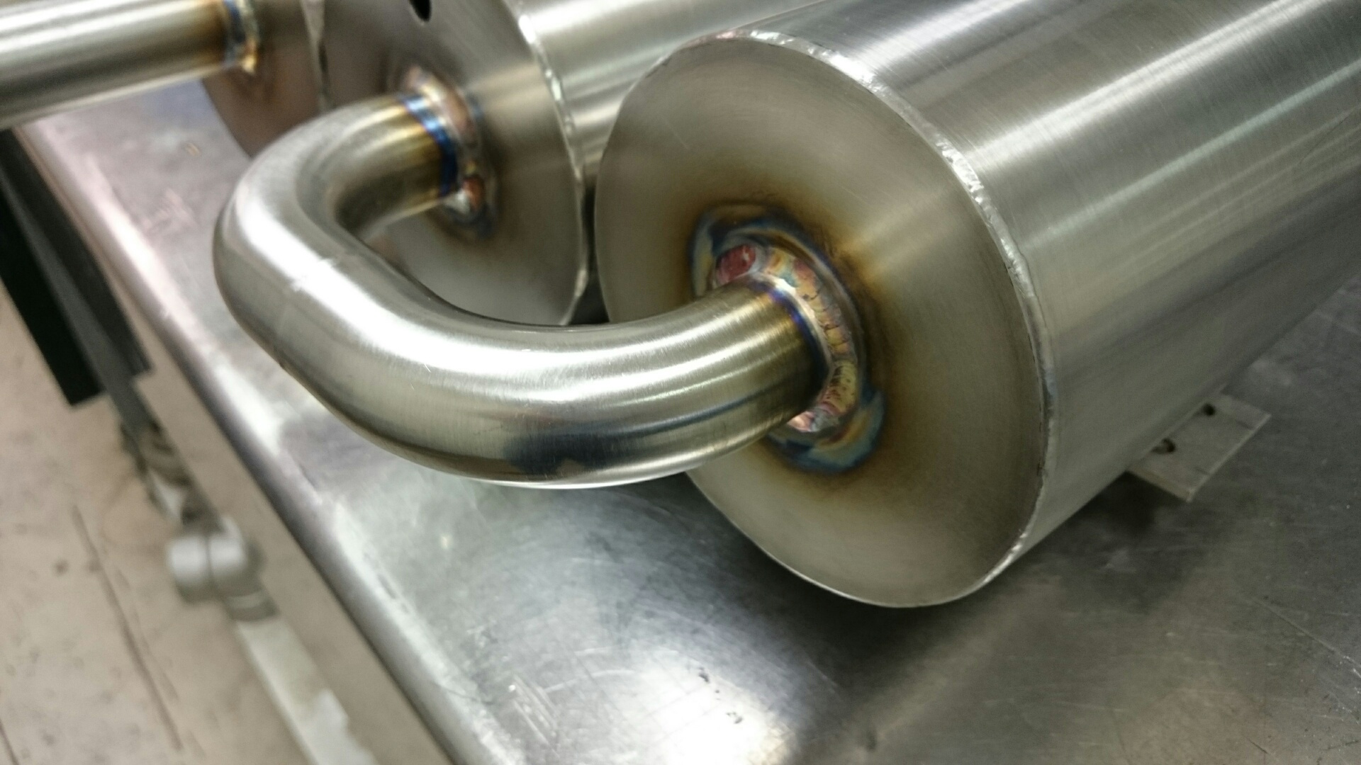
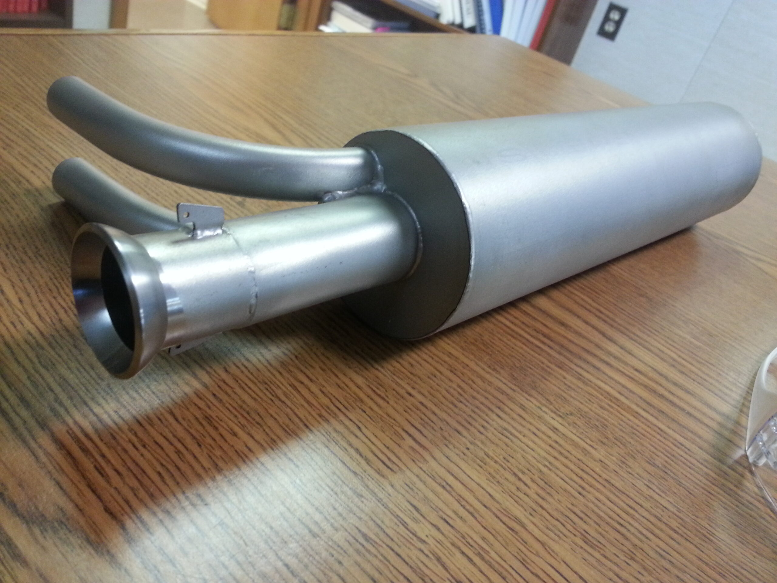
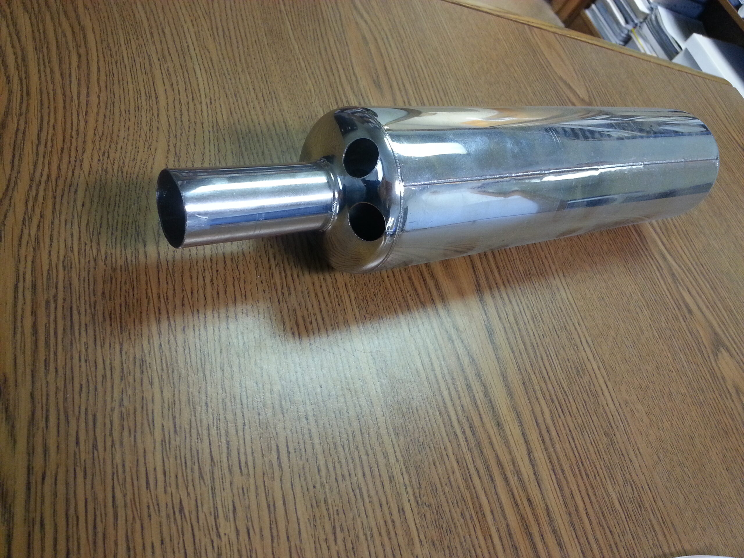
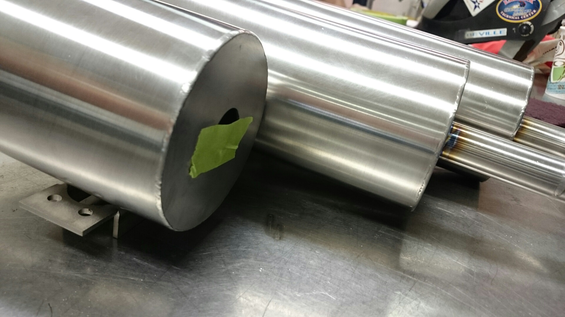
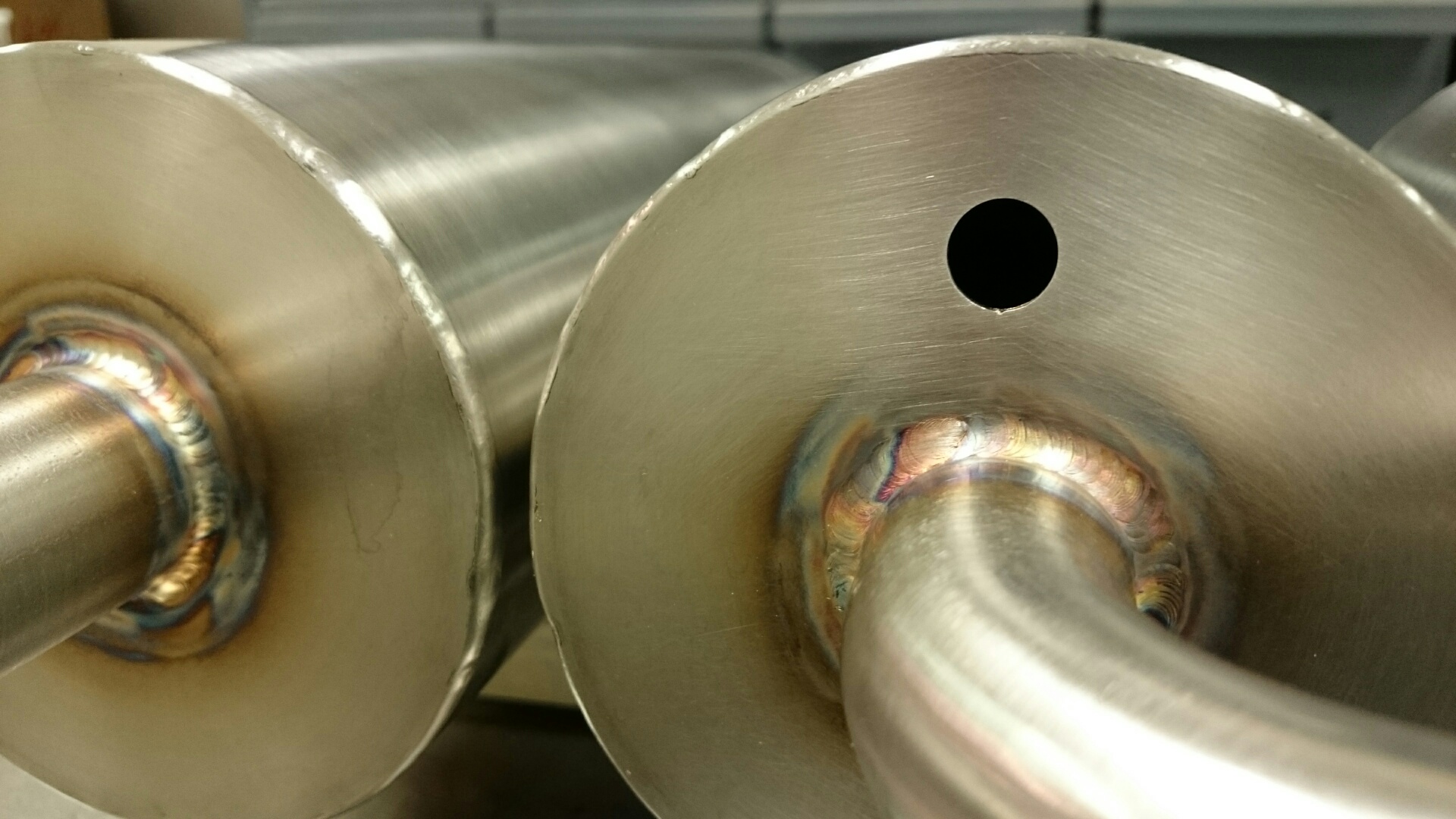
The resulting muffler was a canister type with three tubes stemming from the top; the center tube came with a flare-type connection while the other two were 90° elbows welded parallel to one another. The customer was so impressed with our team’s speed and attention to detail that they recommended us to some of their colleagues, which led to more custom muffler prototypes being manufactured.
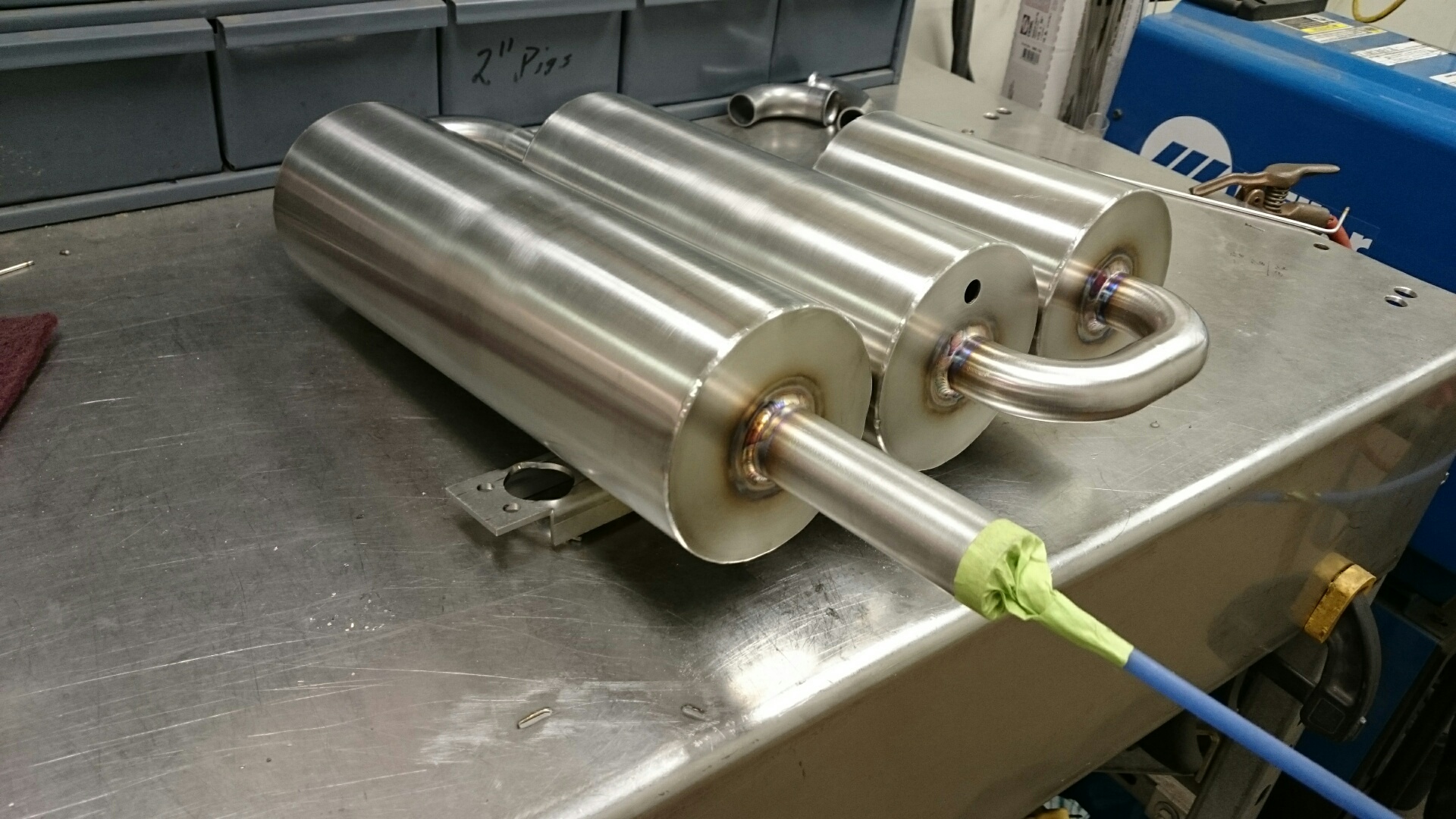
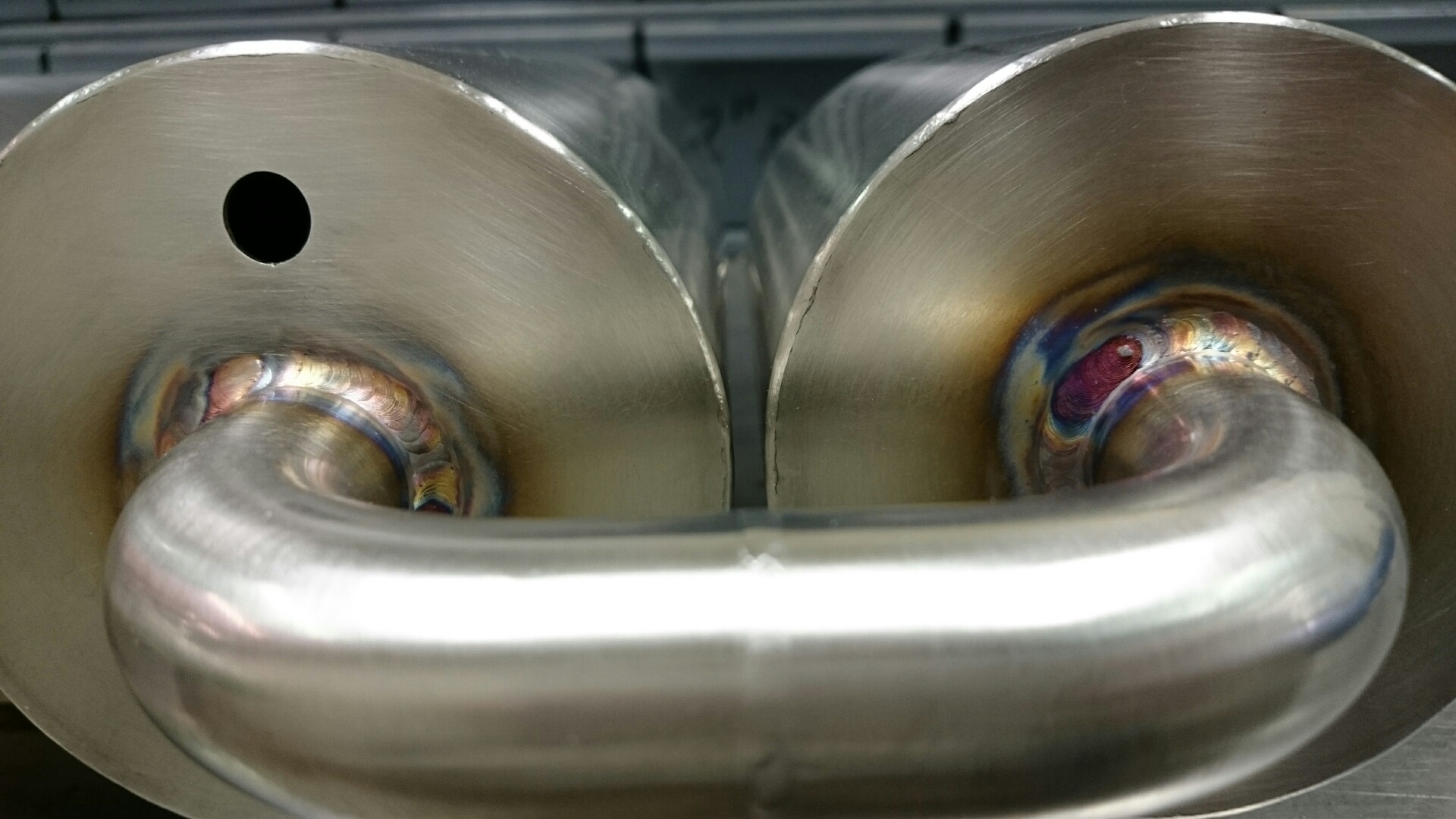
One of the other mufflers consisted of three canisters parallel to one another, welded together with 180° elbows. Another had a larger center canister with a long, straight tube on top and, next to that, a long 90° elbow that needed a flexible end on it.
Additionally, one customer wished to install what could only be described as small-bore flex duct. Our team quickly determined, however, that not only was this ducting too heavy to be feasible, but it would also be nearly impossible to weld because of the spiral casing. Instead, we suggested using a much lighter thin-wall vacuum bellows, giving our customer the final functionality they desired and leaving them eager to have HPS fabricate more mufflers for them in the future.
The Result
This array of custom mufflers is just one example of the kinds of fabrication challenges we have helped customers overcome during the R&D process. When designing one-of-a-kind prototypes, it’s crucial to work with a fabricator that has a wealth of experience in bringing the end user’s design to life and then efficiently mass-producing.
If you have a vision but don’t quite know how to bring it to life, let HPS help you.
Contact High Purity Systems
Have a question about a piping challenge? Want to discuss an upcoming project? Let’s talk.
Acid Containment Piping
Leave a CommentThe Challenge
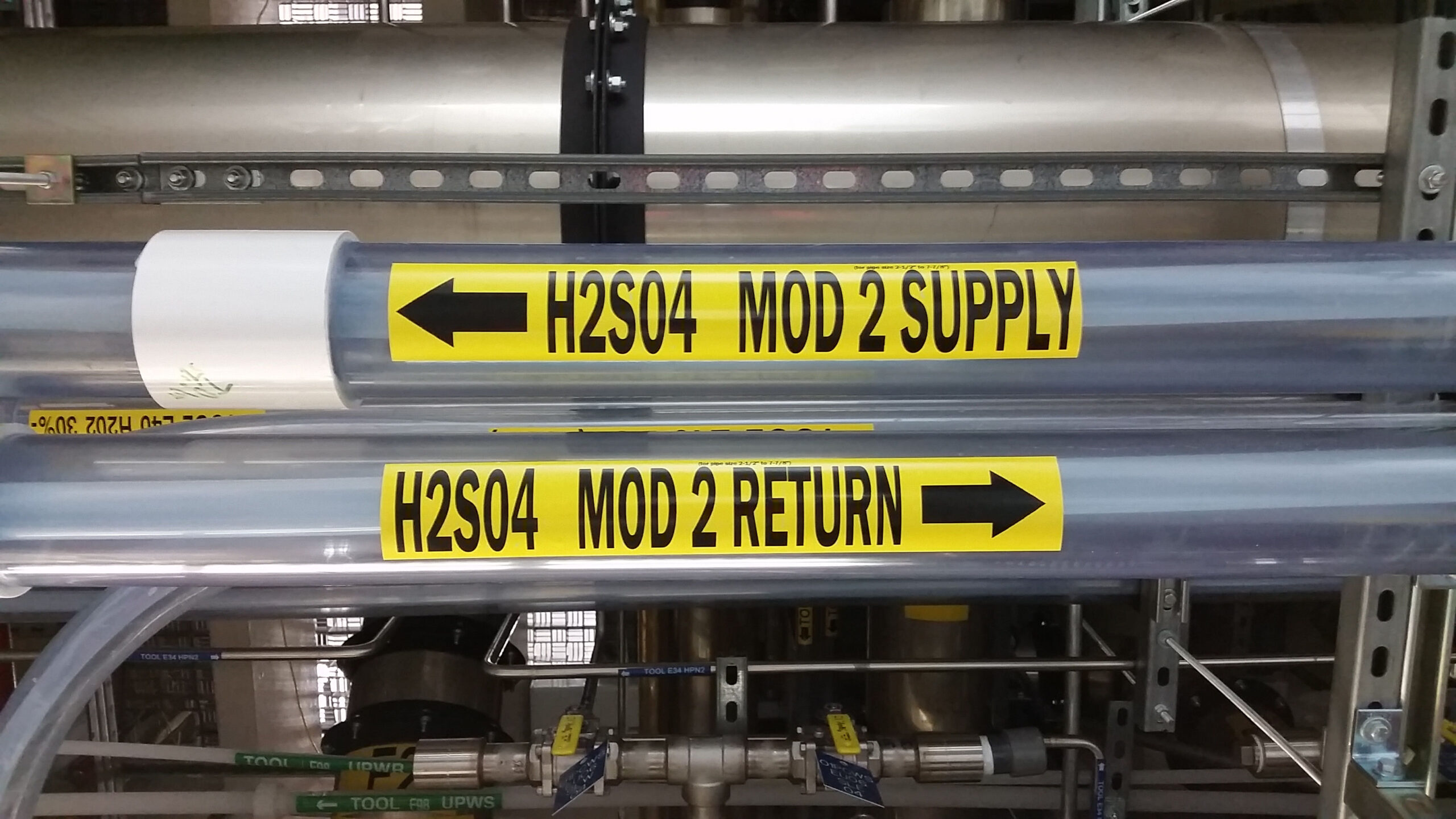
One of our repeat customers — a leader in the semiconductor industry — recently called on HPS to carry out a project transporting concentrated sulfuric acid (H2SO4) from their Virginia facility. The customer supplied us with a drawing of the process piping system they needed to ensure the safe transportation of these hazardous chemicals.
The Strategy
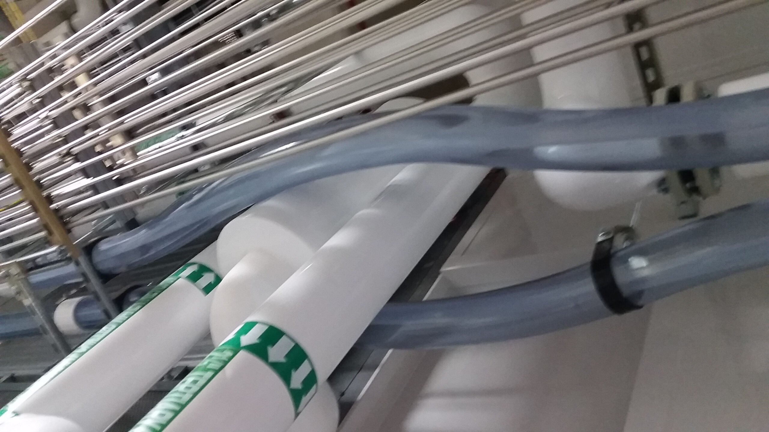
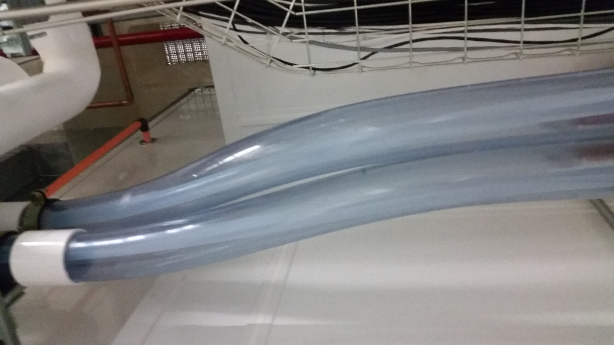
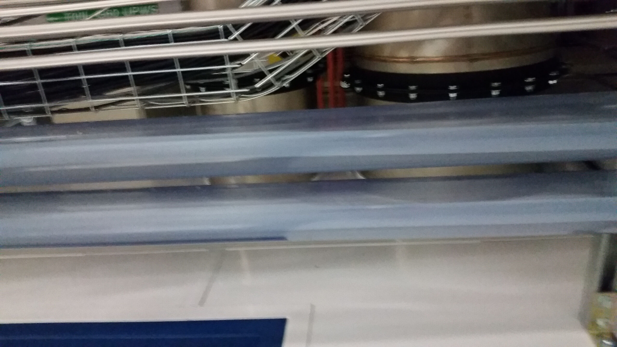
This project involved detailing, fabricating, and installing a double-walled containment piping system with over 900 feet of linear piping for sulfuric acid. The inner carrier piping was made from 1¼” PFA tubing, resistant to sulfuric acid corrosion, while the outer containment piping was made from clear 3” PVC. The double-wall design would allow for rapid recognition and repair of any potential leaks in the inner carrier line. We fabricated the piping according to customer supplied specifications and P&ID, and then sent a field service team on site for a full installation.
Because of the customer’s rapid growth over the last two decades, there was already quite a bit of existing process piping where we needed to install the double-walled containment system. Our crew carefully routed the piping around the obstacles while maintaining a 1” tolerance between the existing chemical and gas piping. During installation, the team wore chemical safety suits for protection against the hazardous conditions and, after completion, the PVC pipe was pressure tested for 4 hours at 4 psi and the PFA tubing was tested for 4 hours at 90 psi to assure system integrity.
The Result
A highlight of this job was the need for our team to do its work while other trades were performing their respective jobs in the same location. Our crew coordinated across several other teams working in the shared space to ensure a smooth and successful installation without any schedule disruptions.
Highly confident in our ability to perform jobs professionally, on time, and on budget, this customer continues to come back to HPS for additional projects. Our team takes pride in every project and our continuous commitment to customers. When we work for you, your needs become our needs.
Contact High Purity Systems
Have a question about a piping challenge? Want to discuss an upcoming project? Let’s talk.
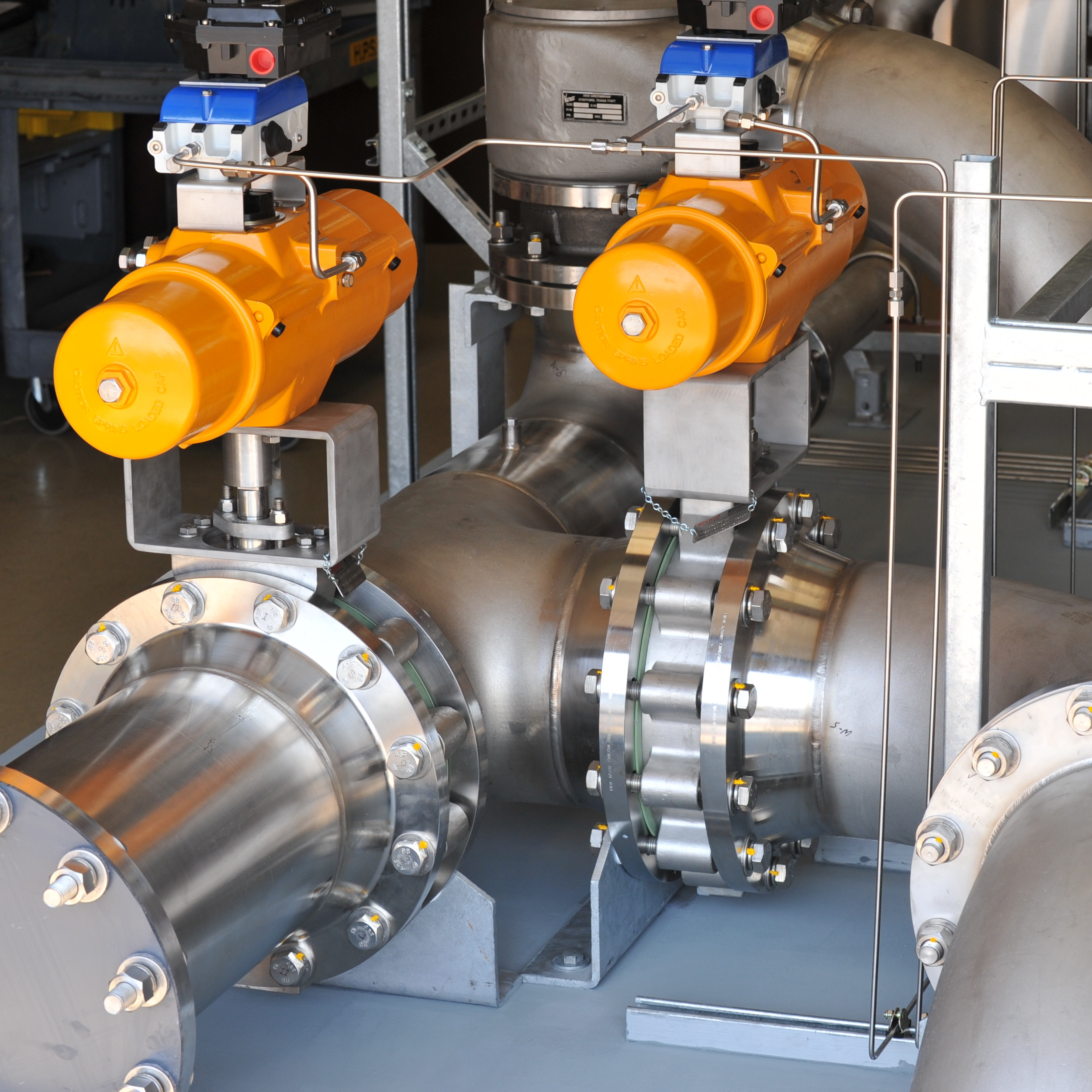
Reverse-engineered inert regulator sticks
Leave a CommentThe Challenge
The ultra-high purity gas delivery systems in microelectronics facilities play a key role in the production of the sensitive components we rely on every day. But the parts that make up these important systems don’t last forever.
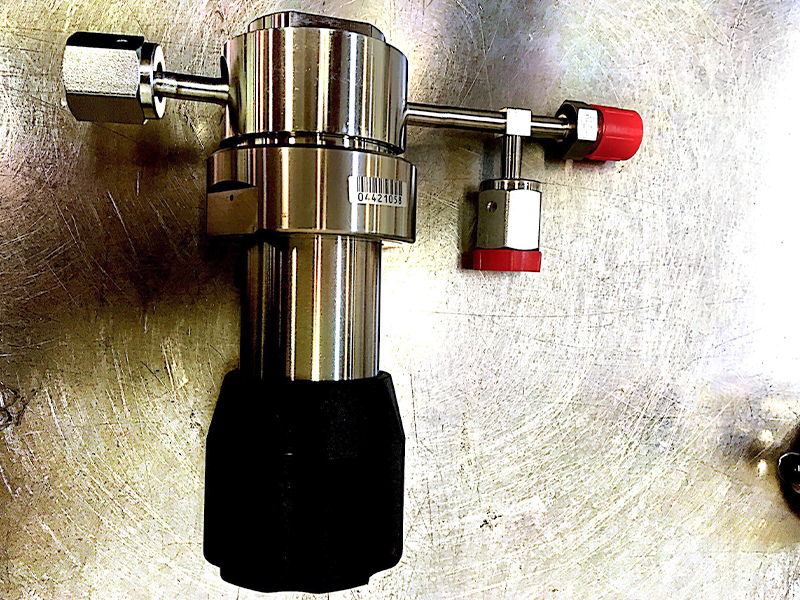
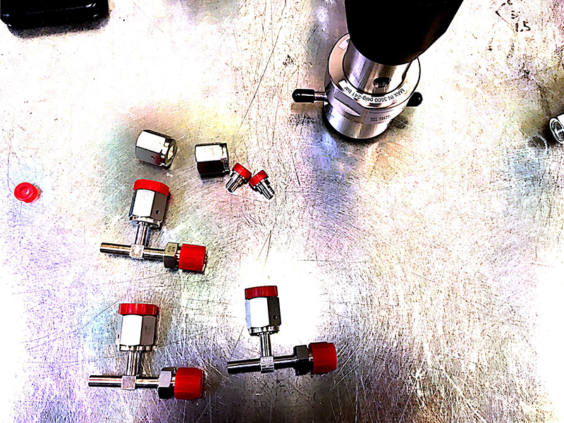
Our client, a major microelectronics component producer located on the East Coast, faced a dilemma: Inert regulator sticks inside ten of their valve manifold boxes were nearing the end of their service lives. Replacements were necessary. The customer had two options, and each was unattractive:
- Order replacement parts from the OEM who made the sticks in the first place. It would take the OEM 20 weeks to fulfill the order.
- Have entirely new valve manifold boxes built—an overly excessive and costly solution.
The customer approached High Purity Systems in search of a cost-effective alternative that wouldn’t result in months of downtime.
The Strategy
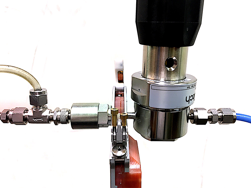
After carefully studying the customer’s drawings and specs for the regulator sticks, our team determined we could reverse-engineer them. Then, we would fabricate in a fraction of the time parts the OEM claimed wouldn’t be ready for almost five months.
Next, we ordered the materials. Because the part would be used in high purity microelectronic manufacturing, we ordered 316L stainless steel components. The elevated chromium content in 316L stainless steel offers improved corrosion resistance over other stainless steel formulas. The wetted surfaces of the components were electropolished to 10 Ra or better, further improving their corrosion resistance.
Then, we fabricated the parts. Due to the sensitive nature of the components, this was done in our in-house Class 100 cleanroom. Our skilled craftsmen used autogenous orbital welding equipment to perform welds meeting ASME B31.3 and SEMI standards.
Obtaining the weld quality you need
Learn about the skills and resources necessary for successful cleanroom welding.
The result
We hand-delivered the regulator sticks to our customer’s plant just ten weeks after we took on the job, cutting in half the time the customer had to go without these critical parts had they engaged the OEM. Most of that time—eight weeks, to be exact—was spent waiting for raw materials with long lead times.
As a result of our quick work, our customer’s facility was back up and running much sooner than they anticipated. That directly translated to a lower project cost and more revenue earned.
High Purity Systems has excelled in understanding customers’ systems—including systems that someone else built. As a preferred alternative to OEMs, we go beyond fabricating replacement parts by helping customers develop their equipment maintenance programs.
Learn more about what to look for in a cleanroom welding contractor by reading our guide on the subject. Then, let’s talk about the difference our expertise can make in your facility.
Contact High Purity Systems
Have a question about a piping challenge? Want to discuss an upcoming project? Let’s talk.
Custom-fabricated port multiplier
Leave a CommentOrdinary solutions are rarely adequate to solve unique challenges.
It hits especially close to home for aerospace firms whose critical research and development efforts push the envelope daily. Developing new parts and components that advance their work comes with the territory.
When a longtime customer realized that a custom-fabricated component would dramatically enhance performance of a system in one of their labs, they turned to someone they trusted.
The Challenge
Our customer is an American aerospace firm with significant research and development capabilities. At issue was a large thermal vacuum chamber the customer used to simulate an orbit environment. Observing how prototypes behave in their intended service environment is a crucial stage in developing satellite missions.
At approximately 30 feet in length and 10 feet in diameter, the original design of the chamber included four feed-through ports connected to the chamber via flanges.
But the customer realized that additional feed-through to the chamber would increase the productivity of the tests conducted inside. It would make the customer’s tests more effective and efficient, potentially providing better test results and quickening mission development timelines.
The challenge was to multiply the chamber’s feed-through capacity while retaining the original four main ports.
The strategy
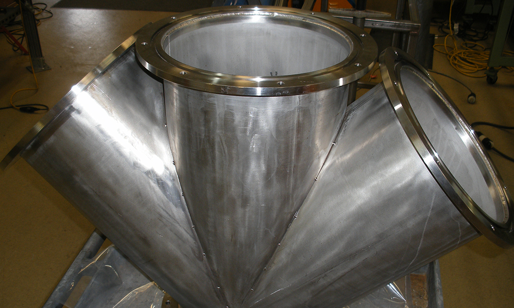
After discussing the circumstances with the customer, our teams agreed the best way forward was to modify the existing ports by adding two branch lines to each existing main line. This would triple the feed-through to the chamber.
Port multipliers aren’t novel, but the customer’s unique project requirements demanded a much larger multiplier than had existed up to that point.
In close collaboration with the customer, our fabrication team got to work modeling the component. Using computer-aided design (CAD) software, we developed a template such that two 12-inch branch lines would be mitered and stabbed into the single central 12-inch line to create the wye. The customer’s design further called for 12-inch flanges on each of two branch lines and on both ends of the existing central line.
All piping and flanges on the custom fittings were made of 316 stainless steel. The bolted-on ports where the feed-throughs attach were made of 6061 T6 aluminum. Due to its shape, the parts took on a nickname: “The tri-wye”—even though it looks more like a Greek Psi (ψ).
Ensuring the pieces fit together proved to be the biggest challenge on the project.
To secure a snug fit, sealing surfaces had to be exceptionally flat and smooth. With our precision machining capabilities, we achieved a total face flatness of just ±0.02 inches. Seal surfaces were ground to a 25Ra (roughness average) sealing finish. The branch lines were level within one-half of one degree.
Next, we hand-fitted the branches and tacked them into place. Then, we welded the branches onto the central lines from the inside via TIG (Tungsten Inert Gas) welding.
Because components within high vacuum systems must be free of contaminants and oil, our team passivated, thoroughly cleaned and dried the interior weld surfaces of the multipliers. The tri-wyes were then shipped to the customer.
The result
Upon installation, the tri-wyes worked flawlessly. The immediate increase in access to the vacuum chamber boosted feed-through and gave the customer an enhanced ability to monitor the conditions inside the vessel.
This project was successful for two reasons. First, our skilled fabricators understood the customer’s objectives and had the resources they needed to do their best work. Second—and maybe more importantly—was our existing relationship with this customer. It’s a tough road earning customers’ trust, but when it culminates in project collaborations like the tri-wye, it’s worth the effort.
What challenges are you facing in your laboratory or production facility? Maybe you have process improvement ideas but need a partner to help work out the technical details and model a solution. If so, we should talk.
Contact High Purity Systems
Have a question about a piping challenge? Want to discuss an upcoming project? Let’s talk.
Custom-fabricated chromatography skid splash guards
Leave a CommentSince 1985, customers have relied on High Purity Systems to fabricate piping systems of all sizes and applications. But they’ve also come to trust our team to solve problems almost entirely unrelated to pipe and piping components.
Such was the case with one of our long-time customers in the Washington, D.C. area. Among the systems at work within this large biopharmaceutical facility are six chromatography skids.
The problem
The skids themselves performed as designed, but significant splash back occurred when they were flushed and drained. This caused compounding problems that put the customer’s productivity and work safety at risk:
- The messes this made meant workers had to do less working and more cleaning, impacting productivity.
- The frequent messes became a persistent safety hazard as floors and other surfaces became soaked.
- The skids were confined to a tight, congested workspace, adding to workers’ safety concerns.
The customer wasn’t sure of a fix, so they called us first to see if we could figure out what to do. After all, we’ve worked with them many times over the years. We know their facility almost as well as we know our own.
The solution
After discussing the problem in the customer’s facility, we determined that they needed splash guards to prevent the messes and eliminate the safety hazards. Because the skids were in such close quarters—and because each skid’s drain piping was uniquely configured—the guards couldn’t be bought off the shelf. Our welders had to custom-fabricate them.
Our fabricators used CAD software to model splash guards for each skid. Some guards were rectangular and some were circular, depending on the configuration of each skid’s drain pipe. The guards included a latch-and-hinge design for easy installation and removal in the tight work space.
The splash guards were fabricated off-site in our shop. We used 316L stainless steel to minimize corrosion risk. Installation of the guards proved tricky given the tight work space. But given our existing site knowledge, we were aware of this challenge from the beginning. Our team installed the guards safely and quickly.
The result
Today, flushing and draining of our customer’s chromatography skids is much cleaner. More importantly, the work space is safer for those who must use it daily. And finally, a strong relationship built on a series of successful projects was further strengthened.
So how do you know who to turn to when a unique problem puts productivity or safety at risk?
Rely on process piping fabricators who are committed to understanding entire facilities and processes. This case demonstrates the value of partnering with a firm whose expertise goes beyond piping to include whole facility problem solving.
If a stubborn issue is holding your facility back from performing at its peak, our team might be able to assist. Contact us now to get in touch with an expert.
Mechanical piping modifications
Leave a CommentInfrastructure inside pharmaceutical manufacturing facilities never goes unchanged for long. Unlike Ron Popeil’s Showtime Rotisserie, you can’t just “set it and forget it.”
As production requirements change and technologies advance, a facility’s processing equipment—and the miles of piping tying it all together—stay in a near-constant state of change.
This was the case in our customer’s facility in Maryland, where two new processing skids were scheduled to replace old ones.
Our crews modified a host of existing mechanical systems to make room for the new equipment before fabricating, installing and piping to tie it in place. And they had to do it without disrupting ongoing operations.
The challenge
The existing process skids in this facility were instrumental in the manufacturing of products found in many medicine cabinets.
But after 20 years, those skids had reached the end of their life cycle. The two new skids our customer had ordered to replace them would add production capacity to the facility—but they had to be tied in first.
The challenge was two-fold. First, the new skids would not fit into their designated space in the facility without extensive modifications to several existing mechanical systems. Second, new rigging and piping would be required to tie the new skids into existing facility services once they were set in place.
Importantly, some of the rigging work needed to be done at height. And, the work would be completed during normal facility operation; even the briefest interruption of production was out of the question.
The strategy
We were selected for the job on the strength of our existing long-term relationship with this customer. Over the last 20 or so years, our crews have delivered 331 fabrication and installation projects in their facility.
It would be a six-month job.
The first phase required modification of existing systems including:
- HVAC ductwork
- Emergency eyewash station relocations
- Backflow preventer relocation
The second phase entailed setting the skids in place and completing 31 tie-ins to the following existing services:
- Steam
- Steam vents
- Chilled water
- Soft water
- Instrument air
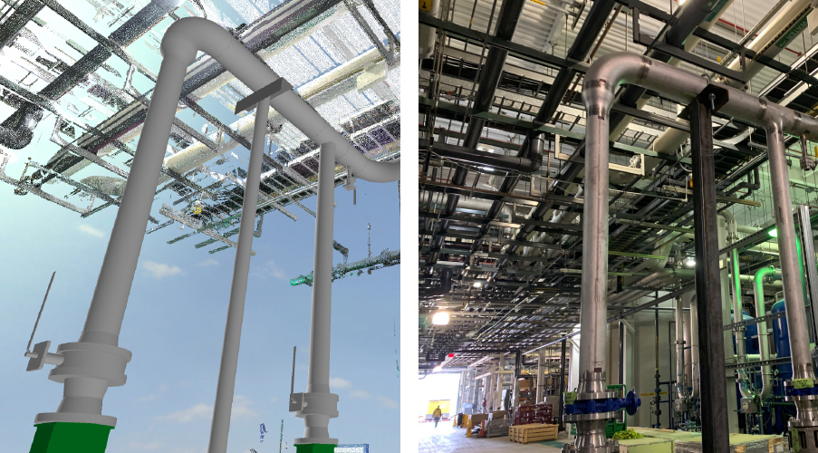
Our team employed laser scanning and building information modeling (BIM) to garner an accurate plan of the work environment and build models of the new skids based on data from the skid manufacturer. The combination of precise measurements and detailed models allowed our shop team to fabricate around 70% of the new system piping in our shop instead of in the field, reducing overall project cost and simplifying installation.
Each skid required 11,000 pounds of rigging, much of which was installed at height. This added another degree of complexity to an already-complicated project, but the risks associated with working at height were minimized by the fact that more than two-thirds of the required welds had been completed in our shop in advance.
The requirement that our installation not disrupt facility operations meant we had to hot tap into a line to add valves without taking it out of service. The challenge was that the line was located near the ceiling just beneath other lines which also could not be moved or shut down. This space restriction meant our craftsmen needed to put their hot tap machine in at an odd angle to successfully tap into the line.
That was the relatively easy part. The harder part was fabricating custom fittings to get the piping back square. The fittings needed to connect the odd-angle coming off the valve on the hot tap to a vertical run that then led to the ceiling rack and eventually tied into the new skid.
We also pre-fabricated a steam station that, once installed, provided easier access to the system’s valves and components.
In total, our team installed 1,600 linear feet of piping. The wide range of work this job required skilled SMAW welding and entailed required working with many different materials, including stainless steel pipe and tube, carbon steel pipe, copper pipe and PVC pipe. All work passed visual weld inspections and system pressure tests.
It all occurred without disrupting facility operations.
The result
Successful delivery of this system modification and skid tie-in project hinged on three key factors.
First, the craftsmen working on this project needed to be familiar with the wide variety of systems and materials involved in this project.
Second, it was also imperative that they knew the ins and outs of this customer’s biopharmaceutical facility. They know the place like the back of their hand, and it helped them deliver high-quality work safely and on-schedule.
Finally, skillful project management was essential. Without it, there would have been no way the project was delivered in time and without shutting down production even once over six months.
In each case, High Purity Systems delivered with uncommon quality and care. If that’s the kind of work you expect from a general mechanical contractor, we should talk.
Contact High Purity Systems
Have a question about a piping challenge? Want to discuss an upcoming project? Let’s talk.
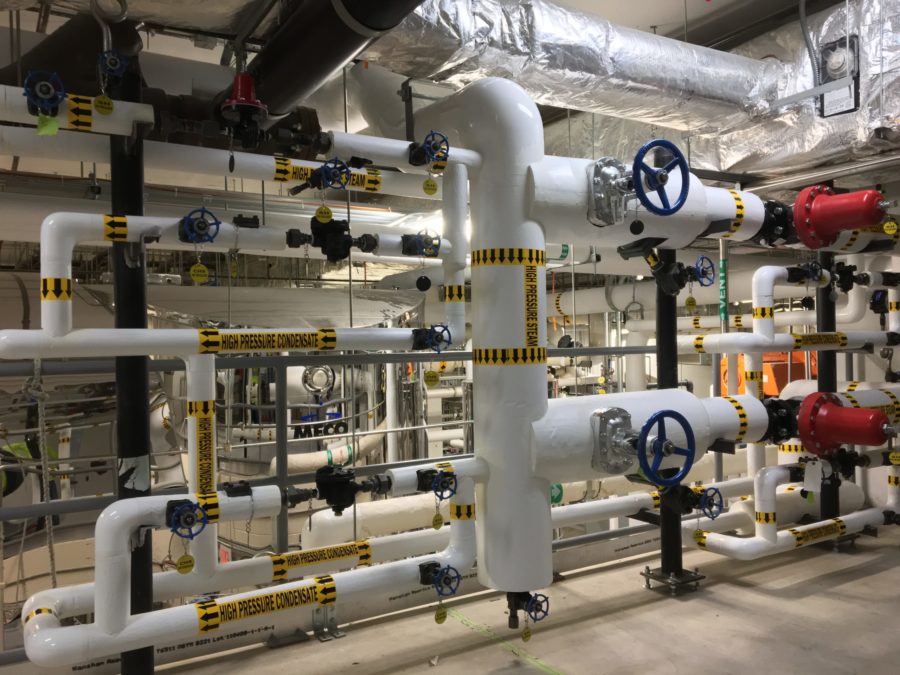
NASA Skids
Comments Off on NASA SkidsThe Challenge
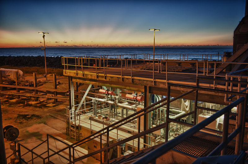
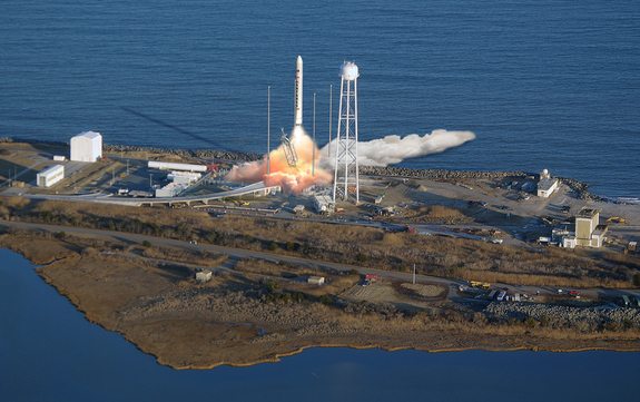
The High Purity Systems (HPS) team was excited for the opportunity to reach for the stars when we were contracted to build fourteen stainless process piping skids for ground support equipment for an unmanned rocket resupply mission to the International Space Station (ISS). Designed collaboratively by a team of engineers who were working directly with our client in Dulles, VA, these skids were integral to the process piping system supporting a Liquid Fueling Facility (LFF) for the NASA launch facility at Wallops Island, Virginia.
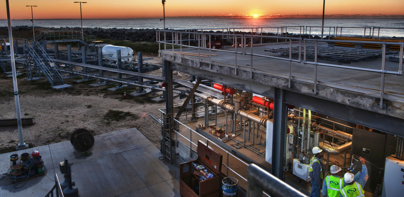
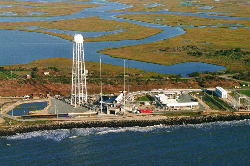
The need for a fueling station arose when NASA began subcontracting their supply deliveries to the ISS. After visiting our fabrication facility in Northern Virginia, it became clear to the engineers working on the LFF project that HPS was the best company to build the process piping skids. As the first of its kind on the East Coast, we are proud to be part of the team that built the infrastructure of the Liquid Fueling Facility at Wallops Island.
The Strategy
We designed the facility skids with job specific components and precise specifications to operate in severe weather and operational conditions in adherence with the critical guidelines set up for the LFF program. Once the final drawings were approved for fabrication, the HPS team commenced production.
We built the skids (some as big as 8’ wide by 22’ long) with structural steel and then they were hot dip galvanized to ensure maximum corrosion resistance. To cut down on conductive electrolysis, we machined and installed micarta laminate sheets as standoffs between the steel supports and the stainless steel piping.
After we removed all possibilities for stainless steel to come in contact with the galvanized steel, we began the piping work. We laid out all the skids in order of schedule priority at our fabrication facility; this made the entire construction and fabrication process as efficient as possible.
The crews had to pay close attention to detail to adhere to welding codes ASME B31.1, as well as severe cyclic criteria for ASME B31.3 process piping. We took extreme care to guarantee that each weld would perform reliably for the life of the system. The project utilized equipment including TIG welders, tube and pipe flaring equipment, and our mandrel pipe bender. By bending the stainless steel pipe, we were able to increase productivity and reduce overall costs of the project.
The official guide to mandrel bending
Separate facts from myths and save up to 50% on project costs compared to cutting and welding.
Because of the one-of-a-kind nature of this project, engineering modifications were ongoing throughout production. With frequent conversations between HPS and the designer to keep communication open and respond to any challenges before they became problematic, everyone worked together smoothly in an effort to produce the best product with the least amount of down time.
Each skid had an inlet and an outlet, with some equipped with more than one. From the inlet flange, the stainless steel pipe system meandered through a series of valves, regulators, and flow meters to meet the outlet flange. Planted over top of the main piping was a system of hangers for more tubing. The ¼” and ½” tubing was bent, flared, routed, and rose together before splitting off to go to its final connection point.
We used some of the tubing to pipe out pneumatic controllers on valves and other tubing to supply pressure to gauges and flow-indicators. Each skid was a cleanly-designed, efficient stainless maze. Once we finished the piping, the electricians mounted switch boxes and finally installed safety shut-offs and indicator lights.
The Result
Thanks to a team effort from engineers, designers, welders and fabricators, the creation of these LFF skids resulted in a successful rocket launch in February 2013. We were truly proud to be part of the ground support effort for this project. With the quality systems that we supplied for this launch pad, HPS was able to reach for the stars — and beyond.
Contact High Purity Systems
Have a question about a piping challenge? Want to discuss an upcoming project? Let’s talk.
Semiconductor reclaim water system upgrade
Leave a CommentManufacturers of all stripes know the struggle of meeting existing production obligations while also ensuring facilities are prepared to ramp up capacity in the face of growing demand.
So when new projects enter the pipeline, production managers walk the tightrope. If they fall down one way, future opportunities could slip away. If they fall down the other, existing obligations go unmet.
When the right specialty piping contractor is involved, no one falls down at all.
The challenge
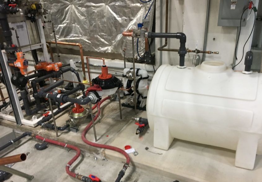
The scenario above applied nicely to a semiconductor manufacturer near Washington, D.C. As demand for their products grew, it was clear in the spring of 2020 that they would need to increase production capacity.
Part of that expansion involved making upgrades to the facility’s UPW, RO/DI and reclaim water systems. That required fabrication and installation of 700 linear feet of new Schedule 10 316L stainless steel pipe. An added challenge was the customer’s directive that the project not cause delays to daily production and take up as little facility space as possible during installation.
High Purity Systems was chosen for the work based on its reputation for delivering quality work and its extensive prior experience with this customer.
The strategy
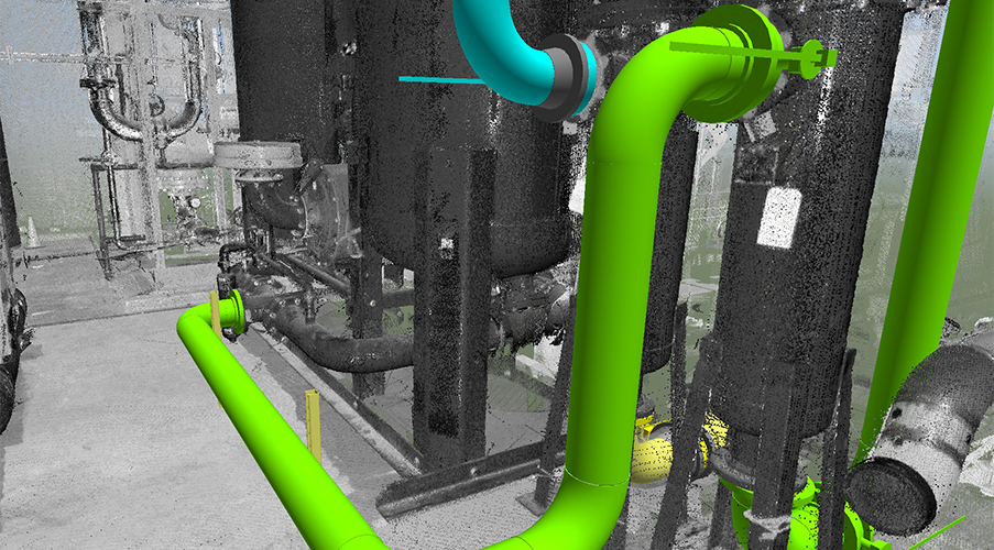
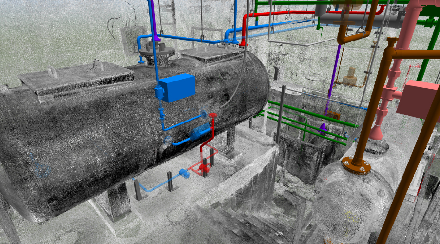
The first step for this project was to take accurate measurements of our workspace. Keeping in mind the customer’s requirement that production be maintained and that the presence of construction crews be minimized, we accomplished this by utilizing laser scanning technology.
Laser scanners shave many hours off the measuring process, and they do it with far better accuracy than other digital methods. (In fact, the laser scanner we use—a Faro S350—is accurate down to one millimeter at 350 meters distance!)
In this case, we scanned an area of roughly 3,000 square feet. This only took one person a single day to complete. Typically, hand measurements in a space this size require two people and takes them twice as long to complete.
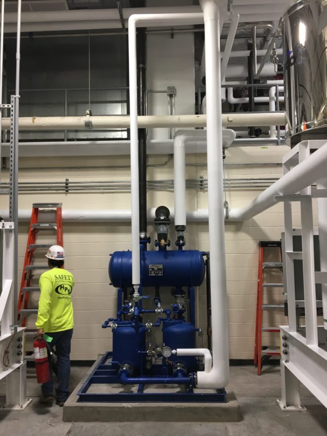
After scanning, our team uploaded the point cloud created by the scanner into BIM software to generate a 3D model of the space. That model became our roadmap. It was so accurate, it allowed for custom shop fabrication of 90% of the project’s large-size piping in our Manassas, Virginia facility. (You can read more about the advantages of off-site fabrication in this in-depth guide.)
After items were fabricated, we shipped them to the site for installation on a just-in-time basis. No need for cumbersome staging of weeks worth of supplies. The only space we took up was for our crew, our tools and material for that day’s work. And, as another testament to the accuracy of our BIM model, every component we fabricated fit perfectly on the first try with no field modifications required.
The result
Accurate measurements, skillful shop fabrication and smart work from our install team contributed to an on-time delivery of this difficult project.
Successful delivery resulted in these key highlights:
- The facility maintained its rigorous production schedule through the duration of the project, resulting in no downtime or lost revenue
- Efficient, accurate laser scanning and BIM modeling contributed to faster fabrication and installation, saving time and money
- Off-site fabrication for this project generated a 20% cost savings for the customer
- The digital models generated on this project added new value for our customer by becoming an instrumental source of accurate facility information usable on future projects of any kind
This project demonstrates the benefits of partnering with the right specialty piping contractor, one who combines technical skill with project management expertise to keep complex projects on track and running smoothly.
What’s next on your facility’s project list? Do you think your space is a good candidate for laser scanning? We’d love to know more—contact us today.
And, you don’t have to have complex piping systems to utilize our BIM service. From large factories to storefronts to a residential basement, we offer it anywhere it can make a difference! Learn more here.
Contact High Purity Systems
Have a question about a piping challenge? Want to discuss an upcoming project? Let’s talk.